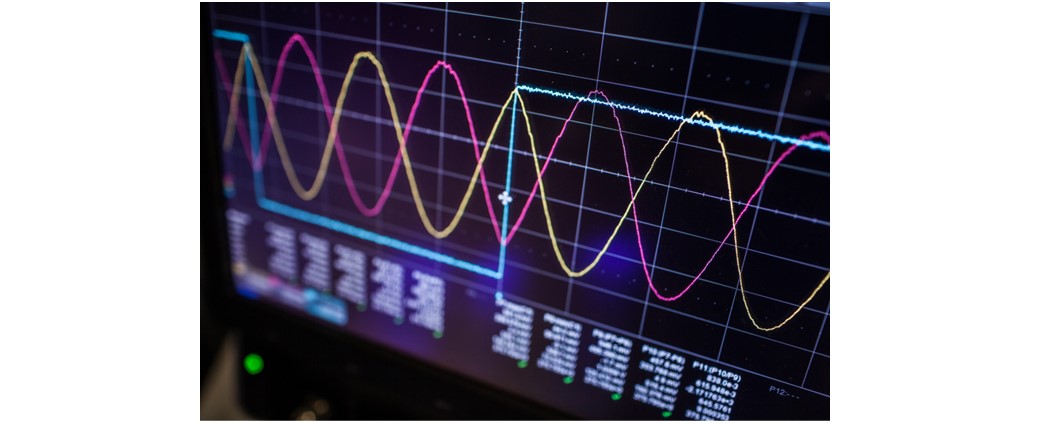
Using Oscilloscopes in High-Speed Digital Design
Oscilloscopes are electronic devices used to observe and measure electrical signals. They are widely used in engineering, physics, and other fields to measure and analyze signals. Oscilloscopes display waveforms graphically, allowing users to see the shape, frequency, and amplitude of the signal being measured. In this blog post, we’ll highlight their critical characteristics for high-speed digital design and go over some factors to consider when choosing an oscilloscope.
What is an Oscilloscope?
An electronic device called an oscilloscope is used to analyze and display signal waveforms. It consists of a display, signal input channels, and controls for adjusting various settings. The oscilloscope creates a graph by tracking the voltage level of an electrical signal over time. This waveform can then be examined to find any potential issues or signal anomalies.
Oscilloscopes can be used to examine signals in a variety of ways. Oscilloscopes are great for analyzing, validating and debugging electrical systems as they allow to observe the signal change over time in the circuits. They may also be used to find defects in damaged radios, televisions, and other similar devices. Although coaxial cables are used to feed the signal into the probes of a standard oscilloscope, this does not mean that an oscilloscope can only measure electricity. You can use an oscilloscope to measure almost anything by connecting a transducer, which converts one kind of energy into another. For instance, you could study audio signals with an oscilloscope using a microphone (a transducer that converts sound energy into an electrical signal), study temperature changes with a thermocouple (a transducer that converts heat into electricity), or study vibrations with a piezoelectric transducer (which generates electricity when squeezed).
Types of Oscilloscopes
Oscilloscopes can be categorized into different types based on operation mode and the signal processing technologies, but there are two main types as every electronic equipment can be classified: analog and digital.
Analog Oscilloscopes
They are the earliest form of oscilloscopes and use a cathode ray tube (CRT) to display signals in real-time. Despite the advent of newer digital oscilloscopes, they are still used today for certain applications that require a fast response time and a high degree of accuracy.
Analog oscilloscopes (Figure 1) test equipment by directly applying measured signal voltage to its vertical axis, producing a visual representation on the CRT. These oscilloscopes have intensity and focus controls that can be easily adjusted to improve the display’s sharpness.
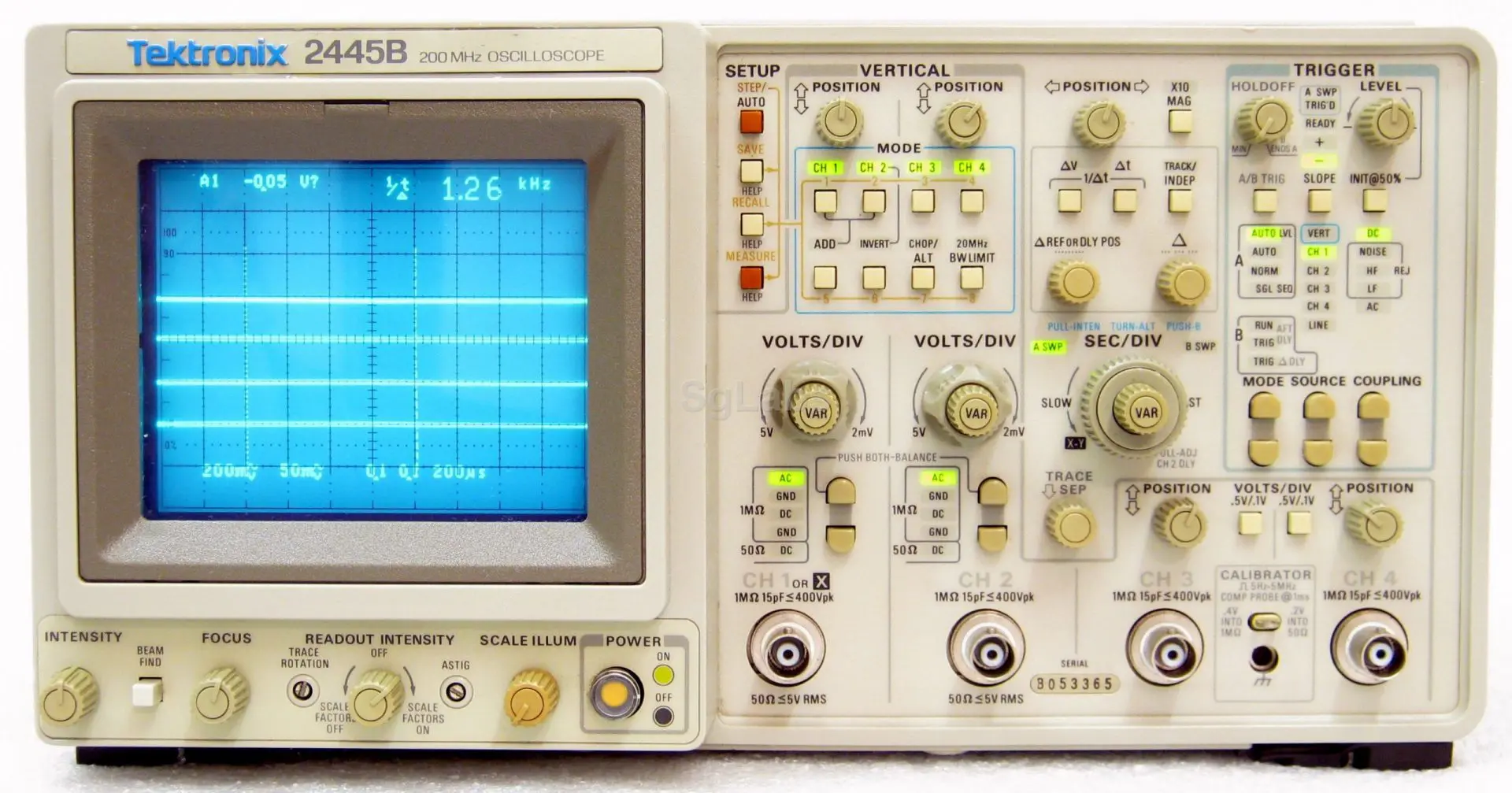
Figure 1: Tektronix 2445B
Digital Oscilloscopes
The main difference between analog and digital oscilloscopes is that in digital oscilloscopes, the analog signal is captured and converted into a digital signal using an analog to digital converter. In turn digital oscilloscopes classified into four parts:
- Digital storage oscilloscopes (DSO)
- Digital phosphor oscilloscopes (DPO)
- Mixed signal oscilloscopes (MSO)
- Digital sampling oscilloscopes
Digital storage oscilloscopes (DSO) (Figure 2) are the most basic form of digital oscilloscopes, its display typically relies on a raster-type screen rather than the luminous phosphor found in older analog oscilloscopes. It converts the analog signal into a digital format and stores it in its digital memory.
DSOs offer several advantages over analog ones. These include the ability to display a transient quantity over a long period of time, easy production of hard copies, signal processing and computation within the instrument, easy transfer of data to a computer, and the use of inexpensive LCD construction. The development of relatively cheap, accurate, and fast A/D converters has made DSOs available for laboratory and industrial use.
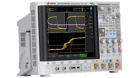
Figure 2: InfiniiVision 4000 X-Series
Digital phosphor oscilloscope (DPO) (Figure 3) is a newer type of oscilloscope that was first introduced in 1998. Unlike digital storage oscilloscopes (DSOs) which use a serial-processing architecture, the DPO uses a parallel-processing architecture that allows it to deliver unique acquisition and display capabilities for accurately reconstructing a signal and capturing transient events.
After the data is stored in the memory unit, it follows two parallel paths. Firstly, a microprocessor processes the data acquired at each sampling instant according to the settings on the control panel and sends the processed signal to the instrument display unit. Additionally, a snapshot of the input signal is sent directly to the display unit at a rate of 30 images per second. This enhanced processing capability enables the DPO to have a higher waveform capture rate and to detect very fast signal transients that may be missed by DSOs.
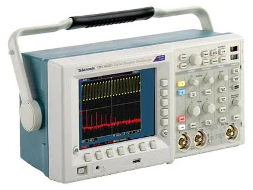
Figure 3: Tektronix TDS3000C
Mixed signal oscilloscopes (MSO) (Figure 4) measure both digital and analog signals simultaneously. Obviously, they have more channels than traditional oscilloscopes, making them ideal for testing mixed-signal circuits.
By combining the analog channels of a scope with the logic channels of a logic analyzer, MSOs provide a comprehensive view of a system’s behavior. While it may not be practical to have a 16-channel oscilloscope, a 2 or 4 channel scope combined with a 16-channel logic analyzer function can provide the necessary capabilities to analyze even the most complex systems.

Figure 4: Tektronix 4 Series MSO
Digital sampling oscilloscopes (Figure 5) use a technique called equivalent-time sampling to measure signals. They are ideal for measuring repetitive signals that occur at high frequencies up to 50 GHz or more, and have low duty cycles. They achieve this by collecting samples from several waveforms and assembling them to build a picture of the waveform.
To optimize for high frequency operation, these oscilloscopes have a different vertical amplifier topology. The signal is sampled prior to amplification to achieve maximum bandwidth. Then a lower frequency amplifier/attenuator combination can be used. However, this reduces the dynamic range of the instrument, limiting the maximum voltage that can be handled to around 3 volts peak to peak.
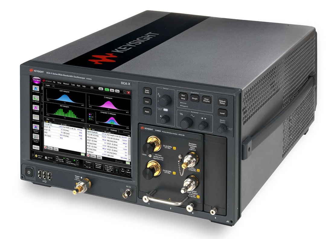
Figure 5: Keysight N1000A DCA-X
Theory of Operation
- An oscilloscope works by converting electrical signals into a visible waveform that can be analyzed. The signal is first fed into the oscilloscope, where it is amplified and displayed on a cathode ray tube (CRT) or digital display. The waveform displayed on the screen represents the amplitude of the signal over time.
- Waveform can be analyzed based on the amplitude, frequency, phase, and other characteristics. The amplitude of a waveform represents the voltage of the signal, while the frequency represents the number of cycles per second. The phase represents the relative timing of the waveform with respect to a reference signal.
- Signal acquisition involves the process of capturing and sampling the input signal. This can be done using a variety of techniques, such as direct probing, current probes, and voltage probes. The signal is then amplified and digitized for processing.
- Once the signal is acquired and digitized, it can be displayed and analyzed using a range of techniques. Oscilloscopes typically offer features such as triggering, cursors, measurements, and advanced analysis tools to aid in waveform analysis.
Choosing the right Oscilloscope
Choosing an oscilloscope can be a daunting task, with a wide range of specifications and features to consider. We suggest some steps which can help you find the right oscilloscope for your application.
Practical Uses of an Oscilloscope in Various Fields
First of all you need to know where you are going to use your oscilloscope and make a list of your use cases, try to think about the following criteria:
- Are you going to use it in one location or will you need light, easy to carry unit?
- How many input channels do you need? Standard is 2-4 channels that you can observe and compare signal timing, but for debugging a digital system you would likely need 8-16 channels.
- What record lengths do you need? A stable sine-wave signal only needs about 500 points and a basic oscilloscope will store around 2,000 points. But, to troubleshoot timing anomalies in a complex data stream, you might need a record length of up to 1 million points.
- Do you want to be able to connect the unit to a computer? Do you need networking, printing and file-sharing abilities?
Budget and Quality
Oscilloscopes vary in price, depending on the brand, model, features and specifications. You should first determine your budget, as this may vary depending on whether you want to purchase the oscilloscope for long-term or short-term use. Then you have to look for the available options in the specified price range. The opinion of other users and experts should also be taken into account in evaluating the reliability of the quality of the oscilloscope. Generally one should avoid unrealistically cheap low-quality oscilloscopes as those would likely yield inaccurate and many times confusing measurements.
Always review the manual and follow the safety precautions before using your oscilloscope.
Second-hand Oscilloscopes
Second-hand or pre-used oscilloscopes are available at over 90% discount over new ones. Also, the equipment that has already been discontinued by the manufacturers can be found as rental units.
As often times there is no way to test a used oscilloscope in person, there are a few details that can be checked to make sure everything is working as presented. The main detail to look for is in the picture of the instrument with an actual waveform shown on the screen – that means the oscilloscope really does work.
You can also zoom in and try to look through the front-panel settings and make sure matches the waveform shown on the screen.
Key Factors and 5X Rule
- Bandwidth
System bandwidth determines an oscilloscope’s fundamental ability to measure an analog signal – the maximum frequency range that it can accurately measure. So try to select an oscilloscope that has enough bandwidth to accurately capture the highest-frequency content of your signals. The 5X rule says that the bandwidth of the scope with the probe should be at least 5X the maximum signal bandwidth for better than +-2% measurement error. For example scopes with a maximum bandwidth of 100MHz can accurately capture the signals up to 20MHz.
- Sample Rate
The sample rate of an oscilloscope is similar to the frame rate of a movie camera. It determines how much waveform detail the scope can capture. Try to select an oscilloscope that has a maximum specified sample rate that’s fast enough to deliver its specified real-time bandwidth.
The 5X rule says to use a sample rate of at least 5X of your circuit’s highest frequency content, because the faster you sample, the less information you’ll lose. For example entry-level oscilloscopes have a sample-rate of 1-2 GS/s and mid-range have 5-10 GS/s.
- Number of Channels
When selecting a digital oscilloscope, you have to consider the number of channels of acquisition. While more channels are generally better for capturing multiple signals simultaneously, it’s also important to balance this with cost considerations. Ideally, you should choose a scope with enough channels to perform critical time-correlated measurements across multiple waveforms with ease. This ensures that you can accurately analyze complex signals and capture all relevant data for your application.
As mentioned above the standard oscilloscopes have 2-4 channels that you can view and compare signal timing, but for debugging a digital system you may need 8-16 channels.
- Memory Depth
Memory depth refers to the amount of data that the oscilloscope can store. It is typically specified in kpts or Mpts (kilopoints or megapoints) and determines the length of time that the oscilloscope can capture a signal.
Select an oscilloscope with a sufficient acquisition memory to capture your most complex signals with high resolution.
- Triggering
Triggering is used to start or stop data acquisition based on a specific event in the signal. Oscilloscopes offer a range of triggering options, including edge triggering, pulse width triggering, and video triggering. The triggering options of the oscilloscope should be suitable for the intended application. Edge triggering is the most basic triggering option, while more advanced triggering options, such as pulse width and video triggering, may be required for more complex applications.
Select an oscilloscope that offers advanced triggering for analyzing even the most complex waveforms. Better triggering options can help you detect challenging anomalies.
- Display Quality
A high-quality display can help you to accurately analyze your signals, especially for complex or fast-changing signals. Therefore, it’s recommended to select an oscilloscope that provides multiple levels of trace intensity gradation, allowing you to see subtle waveform details and signal anomalies.
This is due to the fact that intensity of a waveform can provide important information about how often a signal repeats. By detecting even subtle signal differences early on, you can avoid costly mistakes and improve your design process.
Conclusion
Oscilloscopes are essential tools for testing and debugging electronic systems, and there is a wide range of oscilloscopes available to suit different applications and budgets. When choosing your design partner, whether it is in house or outsourced, it is important to consider how the new design will be validated and tested.
Reach out to us to discuss how we use these tools during testing and validation phase to ensure the success of your next high speed digital design.

