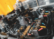
Chip on Board and Wire Bonding Applications
Wire bonding is a standard electrical interconnect technology used in assembling the vast majority of semiconductor packages. It is also a cost-effective and flexible method for attaching a ‘chip-on-board’ directly to a PCB assembly, providing various advantages over using regular ICs.
With a broad experience in utilizing wire bonding and chip-on-board assembly in various embedded systems projects, today we would like to share information about this semiconductor interconnect technique, different wire bonding methods, and how to choose the best fit for your hardware design.
What is wire bonding?
This technology has been widely used in the microelectronics and power electronics industries since the 1970s. As a method of establishing electrical connections between microchips and their packages, wire bonding relies on using a thin wire, which is connected to the surface with a combination of heat and pressure or ultrasonic energy. Wire bonding increases manufacturing flexibility and is used to provide mechanical support to fragile ICs ensuring they will meet requirements of consumer or harsh industrial environments.
Bond wires are typically made of one of the following four materials: aluminium, gold, copper, or silver. Typical bond wires are 15–75 μm in diameter, but they can be up to several hundred micrometres in size when used for high-power wire bonding applications.
Wire bonding is performed using a machine that allows welding the ends of a wire from the microchip bonding pad to the contact pad on the package or PCB. In other words, it is a solid phase welding process, during which two metallic materials – wire and contact pad surface – get connected. When the surfaces of two metallic materials get in contact, welding forms a wire bond.
Wire Bonding Techniques
Wedge bonding and ball bonding are the 2 most common manufacturing methods of wire bonding.
Ball Bonding
Ball bonding is typically used with gold and copper wires. Thus, it requires a combination of heat, pressure, and ultrasonic energy. The process is conducted in a standard way, explained in the previous section of the article: the wires are attached to two points in an assembly to form the connection. The distinctive feature of ball bonding attachment technique is that the first bond is created in a ball shape with the wire sticking out at the top without any directional preferences. This allows the next bond to be drawn in any direction, making the bonding process simpler and faster.
Ball bonding is limited to small diameter wires and has no support of ribbon-shaped wires. It is commonly used for applications requiring electrical connection between a bare silicon die and the lead frame of the package.
Wedge Bonding
Wedge bonding is the most popular and common method of wire bonding. It relies on using a wedge tool to form the stitches on both ends for the first bond instead of a ball, producing thin and wedge-shaped bonds. Unlike with ball bonding, the wedge bonding tool needs to be oriented in the direction of the bond to create it. This is why wedge bonding tools are made rotatable to be able to create bonding from all angles
Wedge bonding supports both ribbon and round wire for bonding, and is more commonly applied for aluminum wire, although it can be utilized for gold wires as well.
The main advantage of wedge bonding compared to ball bonding is that wedge bonds are smaller in size. As a result, this attachment technique is often used for high-power and high-frequency designs, such as chip-to-chip bonding, and applications where ribbon wire is required. The downside of this process is that wedge bonding is slower than ball bonding.
Types of wire bonding based on materials
One way of categorizing types of wire bonding methods is based on materials used to make wire bonds. Let’s look at the most popular ones in more detail.
Gold wire bonding
Gold wire bonding relies on using gold wires that are attached to two points in an assembly to form the connection by utilizing the thermosonic bonding process to form the attachment points for the gold wire.
The gold wire bonding process begins with the formation of a gold ball at the tip of the wire by melting it to create a so-called free-air ball. Which should be roughly 1.5 to 2.5 times of the diameter of the wire in size. After the free-air ball is formed, it is pressed on the heated assembly surface for a certain amount of time to form the weld between the ball and the bond pad by allowing the ball bond into its ending shape.
Aluminum wire bonding
Aluminum wire bonding process is similar to gold wire bonding with several differences. As aluminium wires don’t require the surface to be heated, the bonding is achieved by the means of ultrasonic energy applied for a certain amount of time, which forms the first wedge bond between the wire and the bond pad. Alloyed aluminum wires are generally preferred to pure aluminum for this type of wire bonding due to greater drawing ease to fine sizes and higher pull-test strengths in finished products.
The process of creating an aluminum wire bond is generally the same, with force and ultrasonic energy being the two main factors needed to create the bond.
Aluminum wire bonding has several advantages over the gold wire bonding. Mainly, it allows the formation of the bonds on temperature-sensitive assemblies made from materials that cannot withstand the temperatures required for gold bonding. In particular, this is the reason why aluminum wire bonding is used on aluminum surfaces in hermetically sealed packages that are highly temperature-sensitive.
Copper wire bonding
Copper is the material that is typically used for wire bonding when integrating an IC into a PCB assembly. In addition, rising cost of gold is driving the companies to transition to much cheaper copper. This material also has higher thermal and electrical conductivity as an advantage. At the same time, copper wire bonding is considered to be less reliable due to its hardness compared to gold and is also more susceptible to corrosion.
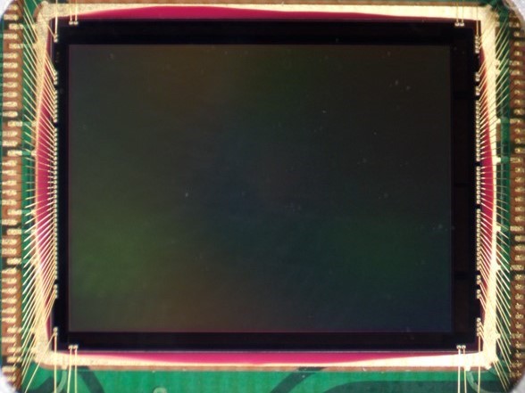
Wire Bonding Chip-on-Board sensor in a Digital Camera System
One of the recent projects executed by Tauro Technologies that involved wire bonding was designing an industrial 8K camera system. To meet the packaging and environmental requirements the high-resolution OmniVision OV48C Chip-on-Board sensor was attached to the printed circuit board (PCB) assembly using the wedge bonding technique. Wire bonding offered greater flexibility, higher precision and was a key component to the success of the camera system development project.
Chip-on-Board Assembly Advantages
Chip-on-board assembly provides several key advantages for high-volume embedded and IoT products
Space Optimization: Direct die attachment eliminates IC package footprint, enabling compact designs for space-constrained applications.
Cost Efficiency: For very high production volumes, COB assembly reduces per-unit costs compared to packaged ICs while maintaining performance.
Thermal Performance: Direct thermal coupling to the PCB improves heat dissipation vs packaged ICs.
Summary
Drawing on the specific needs of our clients, we select and apply various techniques and chip-on-board assembly methods for electronic product development and manufacturing in order to achieve the desired result. Wire bonding is just one example of the comprehensive embedded systems design toolkit that has to be utilized in order to produce cutting edge embedded solutions.
Our team of electrical engineers and designers has a proven track record of successfully designing custom hardware for various kinds of products in multiple technology fields. Utilizing our in-house PCB assembly and debug expertise, we are able to build and evaluate various kinds of specialized electronic devices, rapidly and cost-efficiently.
Get in touch with us for details if you need rapid prototyping, turnkey product development, or specialized semiconductor packaging solutions for your embedded system projec.